Cathodoluminescence (CL) Imaging for Defect & Material Characterization
Cathodoluminescence (CL) is a combination microscopy and spectroscopy technique that produces high-speed spectral maps of optical emissions with nanoscale resolution.
It is used to probe diverse features and properties of materials and devices, from the internal structures of direct bandgap semiconductors to surface plasmon resonances in metallic nanoparticles.
Cathodoluminescence (CL) is the emission of light from a material when it is bombarded by an electron beam, typically within a scanning electron microscope (SEM). This technique reveals critical information about a material’s band gap, crystallinity, defects, impurities, and carrier concentration, going beyond what standard elemental analysis provides.
CL offers high spatial resolution (up to 100 nm) and allows for 2D imaging of these properties across the sample. By adjusting the SEM’s accelerating voltage, the depth of analysis can be tuned. The method supports a broad spectral range from 200 to 1600 nm, and SEM images ensure precise targeting of the analysis area.
Our Process
Sample preparation
Use solid, vacuum-stable samples. Cross-sections or plan-view, depending on analysis needs.
Electron Beam Excitation
An electron beam hits the sample in an SEM, causing it to emit light.
Light Detection and Mapping
CL light is detected (200–1600 nm) to map defects, impurities, and band structure.
Data Analysis and Interpretation
High-resolution images and spectra reveal material quality and crystalline defects.
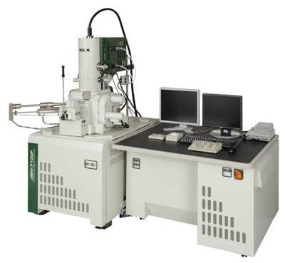
CL Instrument Used
Wavelength Range: 200 – 1600 nm
Acceleration Voltage: 0.5 – 30 kV
Beam Current: up to 300 nA
Measurement Area: 500 nm2up to 1 mm2
Temperature Range: Room Temp (~ 25 ⁰C)
Cooling Unit can accommodate temperatures down to 30 K
Cathodoluminescence Spectrometer is a Toray Original high-speed UV-Vis-NIR CL System based on HORIBA Jobin Yvon
CCD
Photomultiplier (visible and near-infrared EM radiation)
InGaAs multi-channel detector
Detectors
Strengths
High speed spectral mapping
High spatial resolution
Wide wavelength range
Suitable forin situdevice analysis
Specialized accessories accommodate cold experiments down to 30 K
Limitations
Maximum area measured can be up to a millimeter scale
Sample will receive some damage by the electron gun
Organic materials are not ideal
Your Material Analysis Begins Here
Our team of experts is ready to provide a detailed and accurate quote tailored to your specific project requirements